IFR Taxi Check
While taxiing an aircraft in preparation for an IFR flight, make the following checks:
- Magnetic compass - swings freely in proper direction
- ASI - reads 0
- Attitude indicator - upright and erect, no relative motion on ground
- Altimeter - within 75 feet of field elevation, set to current altimeter in Kollsman window
- Turn coordinator - airplane turns in direction of turn, ball swings to outside of turn
- Heading indicator - within 5° of magnetic compass and proper indication during turns
- VSI - 0 reading
Pitot-Static System and Instruments
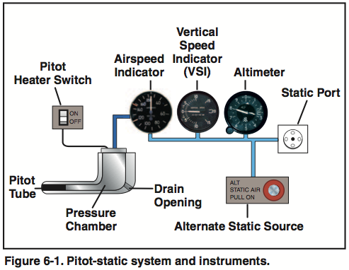
- Airspeed indicator
- Altimeter
- Vertical Speed Indicator
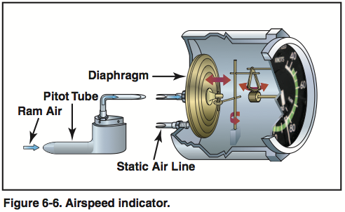
Airspeed Indicator
The airspeed indicator is actually a differential air pressure gauge, and the only instrument which makes use of the impact pressure from the pitot tube. It measures the difference between the pressure from the pitot (impact pressure) and the static source. This difference is registered by the airspeed pointer via mechanical linkage. Note that the difference is 0 when the airplane is stationary on the ground.
Altimeter
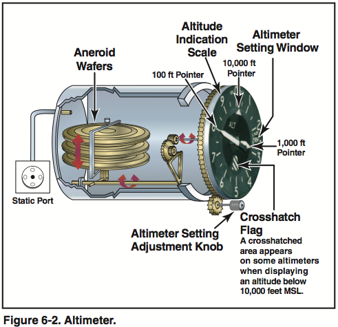
The altimeter contains a stack of sealed aneroid wafers which are surrounded by a casing connected to the static source. As the air pressure varies with altitude, the expansion and contraction of the wafers (due to decreasing and increasing static pressure respectively) is translated via mechanical linkage to an altitude on the face of the altimeter.
Vertical Speed Indicator
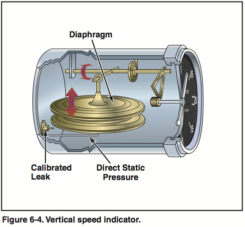
The vertical speed indicator is also a differential pressure gauge, but it uses only the static source. A diaphragm is connected to the static source, as is the surrounding instrument case. However, the case is connected via a restricted oriface (calibrated leak), so it does not equalize as quickly to pressure changes.
Thus, when the airplane ascends or descends, the diaphragm expands or contracts immediately, but the instrument case pressure changes more slowly, registering a pressure difference which is translated via mechanical linkage to the face of the instrument.
Blockages in Pitot Static System
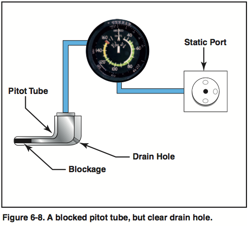
- If the pitot becomes blocked, but drain hole is clear, air will vent through the drain hole and remaining pressure will drop to ambient pressure, reducing the airspeed indication to 0.
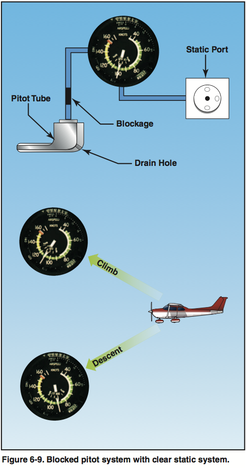
- If pitot, drain hole, and static system all blocked, no changes in airspeed will be indicated.
- If pitot and drain are blocked but static is clear, ASI acts as altimeter due to an apparent increase in ram air pressure relative to static pressure
- If static system blocked but pitot is clear, ASI operates but is inaccurate. Indicated airspeed is slower than actual when above altitude where static was blocked and vice versa.
- Blocked static system causes altimeter to freeze at altitude where block occurred and produces continuous 0 indication on VSI.
Vacuum System
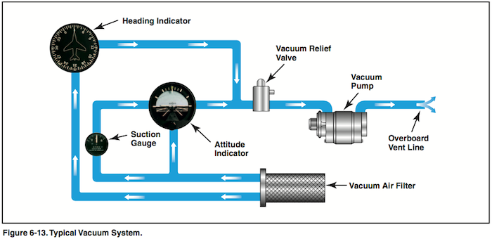
In most non-glass cockpit aircraft, a vacuum pump pulls (or in some cases, pushes) air through a plumbing system to spin up and drive the following gyroscopic instruments:
- Attitude indicator
- Heading indicator
Two primary kinds of vacuum pumps are dry and wet vacuum pumps. Wet vacuum pumps are more expensive, but significantly longer lasting and more reliable than dry vacuum pumps. Dry vacuum pumps are much more common and prone to failure at around 500 hours in service. The primary functional difference is that dry vacuum pumps use carbon fiber tips on the spinning ring to generate a vacuum within the case whereas wet vacuums use a thin layer of oil such that the tips never actual touch the case.
For further details, read Wet vs Dry Pump on N252Q.com.
Attitude Indicator
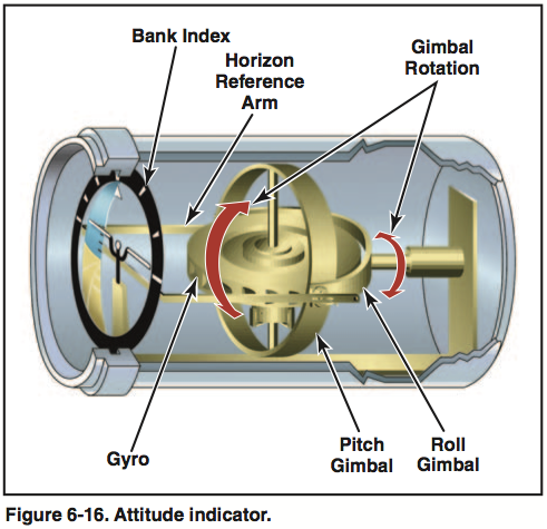
The attitude indicator gyro is mounted on a horizontal plane and depends on the rigidity in space principle. A bar is attached to the gyro and remains in a horizontal plane as airplane is pitched or banked around it, giving the indication of the airplane's current flight attitude with respect to the miniature airplane and instrument face.
The attitude indicator is subject to certain errors. A skidding turn followed by a return to straight-and-level, coordinated flight, will then indicate a turn in the direction opposite the skid.
Also, movement of the vanes by centrifugal force during a normal, coordinated turn causes precession of the gyro toward the inside of the turn. The error is most apparent in a 180° steep turn. A 180° steep turn to the right followed by rolling the aircraft straight-and-level flight will show a slight climb and turn to the left. This precession error, normally 3-5°, is quickly corrected by the erecting mechanism.
Heading Indicator
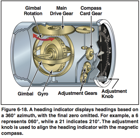
The heading indicator also depends upon rigidity in space. The gyro is mounted in the vertical plane with a compass card fixed to it. Because the gyro remains rigid in space with respect to the vertical plane, the card provides heading information as the airplane revolves around its vertical axis.
Turn Coordinator
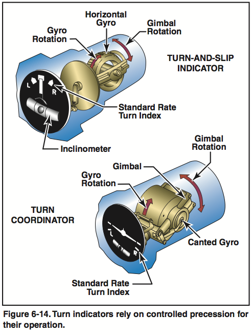
The turn coordinator is typically powered by the electric system, thus making it an independent source of information with respect to the AI and HI. The gyro rotates in the vertical plane and the gimbal is canted at about 30° allowing the gyro to sense both rate of roll and rate of turn. The turn coordinator relies on the principle of precession.
As the aircraft rotates about the yaw or roll axis, the principle of gyroscopic inertia causes the gyro to resist the change in its rotational axis about the free axis. This resisting force works against a spring; thus, a slow rate of turn deflects the gyro slightly while a higher rate of roll or yaw deflects it more. The gimbal is linked to the indicator dial on which is the rear view of the miniature airplane. From Wikipedia.com.
Magnetic Compass
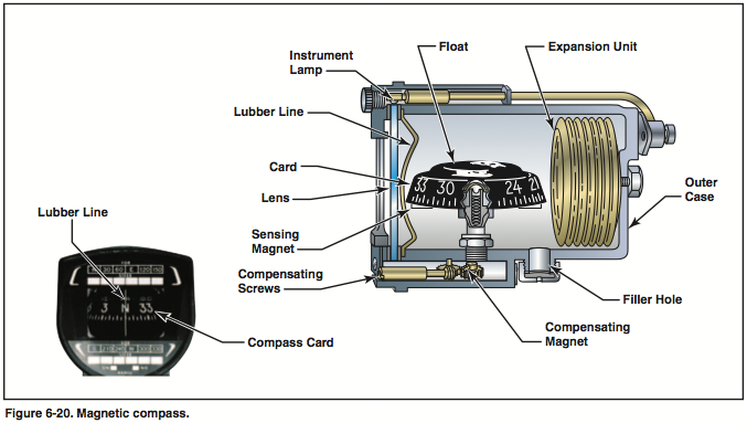
The magnetic compass contains two steel magnetized needles fastened to a float around which is mounted a compass card. The needles are parallel with north-seeking ends pointing in the same direction.
Because of magnetic dip (the vertical component of the Earth's magnetic field), the mag compass displays certain errors in turning and acceleration. Briefly those are:
- ANDS - Accelerate North, Decelerate South - compass swings to the north during acceleration and to the south during deceleration
- UNOS - Undershoot North, Overshoot South - when turning to a north heading, undershoot the desired heading and overshoot when turning to a southern heading
- NOSE - North Opposite, South Exceeds - when turning from a north heading, turn initially indicated opposite direction and from a south heading, it is in the correct direction but exaggerated
Timed turns:
- Standard rate turn is 360° in 120 seconds = 3° per second
- Take number of degrees you must turn, divide by 3, and the result is the number of seconds you must turn at a standard rate to reach the desired heading
Worth noting that vertical compass cards also display some error, but they are less pronounced than that of the magnetic compass.
